


DC 9V SMT Soldering Test Kit Electronic Practice Set
29

 Direct purchase from the factory
Idaniloju sisan

 Ẹbun ọfẹ
 Ilana gbigbe
 Ilana pada
Ẹbun Ọfẹ
Kaabọ si Roymall, oju opo wẹ ẹbun rẹ. A dupẹ lọwọ rẹ, a si pese ẹbun ọfẹ pẹlu eyikeyi rira. Ṣetan lati ṣawari akojo wa? Yẹra ni koko wa, fi aṣẹ rẹ sii, ki o si gba ẹbun ọfẹ rẹ.Ilana Gbigbe
A nṣe awọn aṣẹ laarin ọjọ 2.Gbigbe deede jẹ ọjọ 5-7.Akoko gbigbe le yatọ da lori ibudo.1. Ilana Pada
A gba nikan awọn nkan ti a ra lati roymall.com. Awọn ẹbun ọfẹ ko le pada. Nkan gbọdọ jẹ ailohunsi ati ni apoti atilẹba.A nṣe awọn pada laarin ọjọ 3-5 lẹhin gbigba.Awọn nkan aṣa ko le pada.Kan si wa: service@roymall.com tabi Whatsapp: +86193598494712.Ilana Isanwo
Iwọ yoo gba isanwo lẹhin gbigba nkan. A ko san owo gbigbe pada.Kan si wa: service@roymall.com tabi Whatsapp: +8619359849471
{"code":"00","result":"


Description:
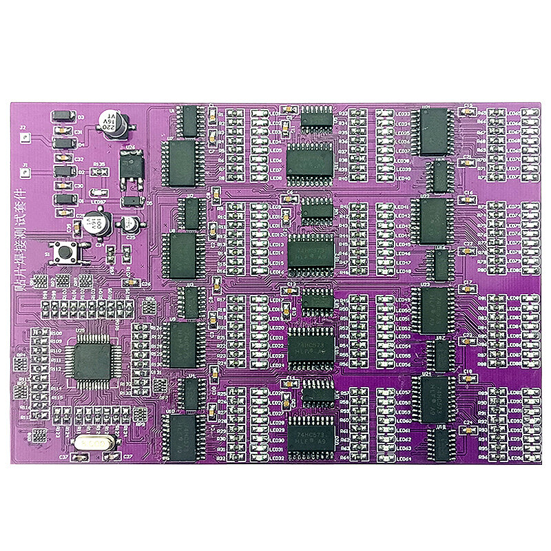
1. J1 and J2 are the power supply input terminals of the entire SMT board. It can work normally when connected to AC6V or DC9V. When working normally, all LED lights in this kit can work normally. At first, each group of LEDs flashes with water, and then flashes at intervals, and finally all Light up all the LEDs, then flash again, and cycle like this to check whether the LEDs are working and whether they are soldered well. If it is found that the corresponding LED does not flicker, it means that there is a welding error or a false welding.n
2. The AC6V power supply is rectified by D1-D4 diodes, and then through each filter capacitor to pin 1 of the voltage regulator chip 78M05 (LED97 is always on, the rectifier circuit is working normally), and the output of DC5V is supplied to the whole test circuit through pin 3.n
3. This test circuit is controlled by a single-chip microcomputer to work with 12 groups of 8-bit LED lights. Each group is composed of 1 74HC573 and 74HC164. One group can control 8 LEDs, 12 groups in total. Figure 1 is the control schematic diagram of one group. When working normally, all LED lights are on and can flash.
Specifications:
Product Name: SMD Soldering Test Kit
PCB material: FR-4PCB board
PCB size: 145*100MM
patch tape connection test
Power supply mode: DC DC9V
Applicable objects: junior welding patch personnel
Component Description: Common patch components are used
Description:
1. J1 and J2 are the power supply input terminals of the entire SMT board. It can work normally when connected to AC6V or DC9V. When working normally, all LED lights in this kit can work normally. At first, each group of LEDs flashes with water, and then flashes at intervals, and finally all Light up all the LEDs, then flash again, and cycle like this to check whether the LEDs are working and whether they are soldered well. If it is found that the corresponding LED does not flicker, it means that there is a welding error or a false welding.n
2. The AC6V power supply is rectified by D1-D4 diodes, and then through each filter capacitor to pin 1 of the voltage regulator chip 78M05 (LED97 is always on, the rectifier circuit is working normally), and the output of DC5V is supplied to the whole test circuit through pin 3.n
3. This test circuit is controlled by a single-chip microcomputer to work with 12 groups of 8-bit LED lights. Each group is composed of 1 74HC573 and 74HC164. One group can control 8 LEDs, 12 groups in total. Figure 1 is the control schematic diagram of one group. When working normally, all LED lights are on and can flash.
Specifications:
Product Name: SMD Soldering Test Kit
PCB material: FR-4PCB board
PCB size: 145*100MM
patch tape connection test
Power supply mode: DC DC9V
Applicable objects: junior welding patch personnel
Component Description: Common patch components are used
- Ifihan
- Nipa wa
- Adehun olumulo
- Alaye ẹtọ
- Iranlọwọ
- Bawo ni lati ra
- Esì
- Olutọni ẹbun
Gba awọn iroyin tuntun ati 15% eni kuro lori aṣẹ akọkọ rẹ.
Yan owo

Yan ede
Awọn ọna asopọ: